(250) 372-7676

FEA Stress Analysis Services FEA Services > FEA Process > Linear & Nonlinear FEA >

FEA STRESS ANALYSIS SERVICES | OVERVIEW


Innovex FEA stress analysis services – bucket wheel excavator

When a design is too complex to solve on paper your project may require advanced FEA stress analysis services. Innovex Engineering employs some form of stress testing in almost every project. Our methods can vary from simple hand calculations to testing with multiple types of FEA. Because safety, function, and cost are your top concerns, our FEA stress analysis services can ensure that your design is safe, efficient, and cost effective.

FEA Stress Analysis Services—Tools & Tactics

Our years of experience coupled with state of the art software enable us to validate the safety and function of your design. Advanced finite element analysis tools provide our engineers the means to simulate the performance of a single part (or a complete design) in a virtual environment. We will flag "over design" issues and help you cost-reduce your project before it enters production. Our engineers will likewise pinpoint areas of weakness that stem from "under design" problems.

In simple terms, finite element analysis employs color coded visuals to reveal areas of high and low stress concentration. But a number of factors may affect the problems we find in your component or design. Our primary focus areas include structural stress analysis, heat transfer, buckling risk, vibration analysis, elastic and plastic deformation.

See an example of Innovex FEA in action: FEA – ASME Pressure Vessel Example.

FEA Stress Analysis Services Tools & Tactics

ASME codes are used to guide lift lug design. Our FEA stress analysis services can provide even deeper insight. Innovex has the expert tools and skills to certify most types of lifting devices.

Engineering Certification Specialists

In unison with our FEA stress analysis services, Innovex specializes in product support and design as they relate to industry certifications. We can also use failure analysis to make design changes and improve safety. Our markets include:

INNOVEX FEA STRESS ANALYSIS | PROCESS


Innovex FEA stress analysis services – process

Here we provide some insight into our FEA stress analysis process. First, in order to solve complex industrial design problems, we use the latest finite element analysis software. We also employ frequent training and industry validation to keep our FEA team at the leading edge. When combined with daily practice in all types of projects, constant training further enables us to produce fast, accurate, consistent results.

FEA Model Creation and Simplification

To create a good model from scratch (or to simplify an existing model) we remove features and parts that will not affect simulation results. This may involve suppressing a large portion of the model, or adding material to fill irrelevant holes. Areas that may cause software instabilities are also fixed during this process. For instance, removing short edges and faces, or adding small fillets to sharp corners.

There are three main reasons why we simplify an FEA model. Speed, accuracy, and stability. When we remove small, less important features such as short faces and edges, we increase FEA stability. Thus the amount of time it takes to run a simulation can be greatly reduced based on how much of the original CAD model can be simplified. Removing unnecessary parts plays a large role in terms of speed. Removing or optimizing features that create an excess of mesh elements can further reduce overall time. Adding fillets and elements to corners while the mesh increases can eliminate corner inaccuracies. In our FEA stress analysis services, though, we use this tactic sparingly.

Meshing

Innovex FEA stress analysis services –meshing

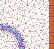
In order to run an FEA simulation the software must discretize the model into small shapes ("elements") that connect at the element nodes. Simply put, a higher amount of nodes and elements results in higher mesh accuracy. The number of elements and nodes in the model therefore determines the number of calculations. Simulation compute time can range from an hour to several days. Because the meshing process is a fine balance between accuracy and time, our goal is to determine the proper amount of mesh refinement in the areas of concern.

Boundary Conditions

Next, model restraints are applied to accurately depict its environment. Restraints may include fixed geometry, hinges, roller/slider, "on faces," reference geometry, bolts, springs, symmetry, etc. Incorrectly applied restraints can vastly alter the simulation results. Over constraining the model, for example, can create nonexistent stress concentrations and overly stiff parts. It can also cause just the opposite result due to an abundance of flex that may actually ignore the high stress areas.

Solving

Choosing the correct simulation solver produces faster results. It can also be a leading factor that determines whether the simulation is accurate or inaccurate. In Solidworks Simulation FEA, for example, the most common solver is FFE. We use FFE for simulations with more than 100,000 nodes. It cannot, however, be used with models that contain instabilities, immediate changes in deflection, or models with excessive contact sets. We use Direct Sparse Solver for small studies with a maximum of 30,000 nodes, or studies containing materials with varying Young’s Modulus values. When direct sparse is required and the model mesh has a vast amount of nodes, we instead turn to Large Problem Direct Sparse.

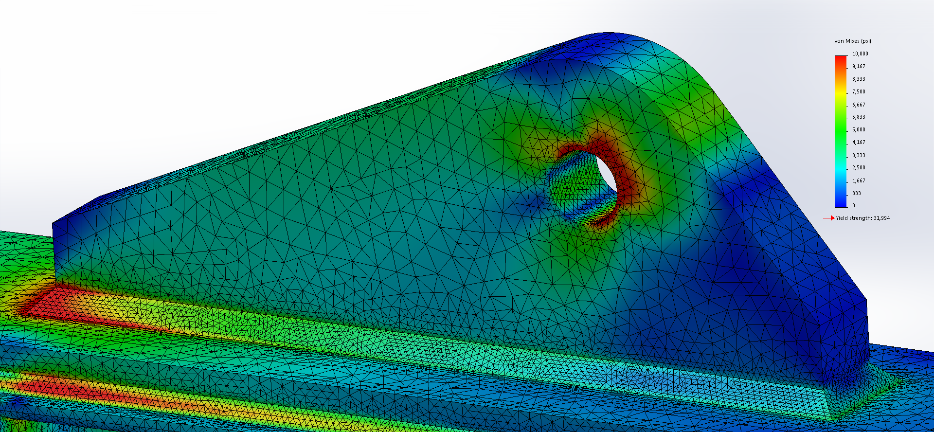
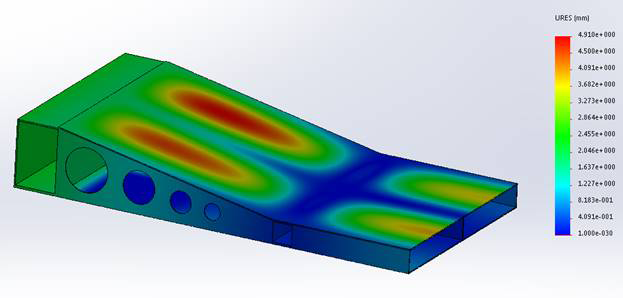
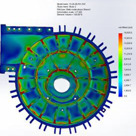
Interpret Simulation Results

Results can be output in many forms. They include: factor of safety plot, stress plot, displacement plot, strain plot, reaction force, remote interface force, free body force, contact or friction force, connector force, result comparisons, and mesh details. Innovex FEA stress analysis services obtain further results through result simulation probes, sensors, and orientation plots such as vertical displacement.

Accuracy Check

Multiple criteria must be satisfied before the mesh is approved. Achieving an accurate mesh—the crucial step—is often overlooked by amateur users. Examples: checking the model for skewed element aspect ratios, error plots, stress gradients, and mesh independence plots. The ideal element aspect ratio is 1, which means all sides of the element are of equal length. Due to holes, edges, and other geometries, the ideal ratio cannot always be achieved. It is ideal to have at least 95% of the elements less than a 3:1 ratio, and zero elements above 10:1, as skewed elements can cause large interpolation errors.

The Energy Norm Error plot depicts the error percentage with regard to the difference between nodal and element strain and stress. When the plot determines Large Error in a group of elements, it means that the node stresses vary vastly from the Gauss points. Additional refinement is therefore required to reduce the extrapolation. Smooth stress gradients provide a quick visual model check to confirm the mesh is reaching independence. It should also be used as an overall check. For areas of concern, a mesh independence plot compares element, or node stress values, to the total amount of elements or nodes in the entire model. When stress value change is negligible after adding numerous amounts of elements to the mesh, the model has most likely reached mesh independence.

BENEFITS OF LINEAR vs. NONLINEAR FEA


Benefits of linear FEA vs. nonlinear FEA

Linear finite element analysis is used for material that stays below its yield point. This type of simulation is relatively easy to setup and quick to obtain results. Linear analysis is also easier to validate with hand calculations.

Nonlinear FEA is used for materials or geometry that change throughout the simulation. Material change occurs when the model exceeds its yield strength. Geometry change occurs when the model shape changes drastically during the simulation due to loading.

Limitations of Each Tool

Linear FEA must have a linear material (stress proportional to strain) and insignificant geometry changes. It cannot have loads or restraints that alter. Nonlinear FEA is limited by extreme distortion scenarios and also through an excessive amount of nonlinear contacts.

Examples of Geometric Nonlinearity

A part that deforms more than half its own thickness needs to have its stiffness re-evaluated due to the change that large change in its geometry. High pressure acting on a plate with large spans would fall under this category.

Examples of Material Nonlinearity

All material that exceeds its yield point and approaches its tensile strength is considered nonlinear. Between these points the material undergoes permanent deformation and its stress values are no longer proportional to its strain. This includes permanently stretched metal, or an excessive load that permanently compresses a piece of rubber.

Benefits—FEA vs. Hand Calculations

Innovex FEA stress analysis services – hand calculations

Hand calculations are used whenever possible. They are the preferred method for simple and quick calculations, and necessary even in complex scenarios where FEA is preferred. Validation is the primary reason. Calculating a simple free-body diagram and comparing it to the simulation can ensure that the simulation is on the right track. Hand calculations alone, however, will not easily show detailed information and accuracy when using FEA on complex simulations.

Our engineers' ability to analyze a part and obtain detailed information on weak and strong points leads to material and strength optimizations. This confidence in the overall design is where our FEA stress analysis services really shine through—and fill a critical role in today's competitive market.

Uses of FEA in Codes (API and ASME)

Codes often allow wiggle room for less conservative designs that are developed with FEA. Finite element analysis can identify weak or problem areas with far greater accuracy than using hand calculations. Some codes in fact require the use of FEA to meet local regulations.

FEA Stress Analysis Services vs. Physical Testing

Physical testing can be a rather expensive process. This is due, of course, to the cost of materials and labor, testing equipment, logistics planning, and finally, the actual testing. It is not uncommon to repeat the test in order to verify design improvements. FEA offers the means to provide just as much insight—if not more—for a lower cost. What's more, FEA simulation can quickly execute multiple tests and test iterations. Environmental conditions, for example, are easily altered. Indeed, performance measurements that would be physically impossible, or too cost prohibitive, fall within reach.

Finite element analysis has by now proved its worth as a valuable tool in the design process. So much, in fact, that FEA stress analysis services play a large role in solving today's manufacturing challenges. At some point in a design’s implementation, physical testing must be employed. But virtual testing and simulation helps our clients speed through the final design stage quickly and more cost effectively.

See an example of Innovex FEA in action: FEA – ASME Pressure Vessel Example.

Industrial Engineering
 Project Developer – Innovex FEA stress analysis services

Industrial Project Developers

Along with CFD and FEA stress analysis services, Innovex provides cordial, cost efficient in-house design and engineering support to OEMs, fabricators, and industrial project developers. With 15 years of expertise in mining, energy and forestry, Innovex can optimize your design for tough 24/7 operating conditions. Please give us a call to discuss your project.